Parts of a Locomotive#
Introduction to the F7#
For the purposes of this guide, we will be working with an F7-A, a very popular locomotive built by EMD around 1950. There may be a few other locomotives used as examples, but the F7-A will be the primary focus.
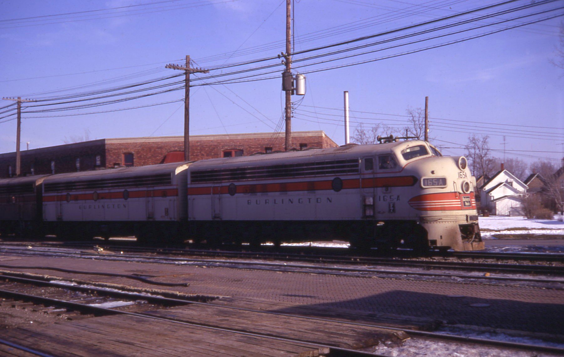
Above: EMD F7-A #165A and an F7-B lead a CB&Q train through Galesburg
More information on the F7:
- This guide's "Valuable Values" page, which includes many specifications for the locomotive
- The original EMD Operator's Manual
- The locomotive's data sheet (courtesy of thedieselshop.us)
Drivetrain#
A diesel-electric locomotive is essentially an electric locomotive with a huge diesel generator on-board. The diesel engine, called the prime mover, turns a generator (or an alternator, in a newer AC locomotive), which creates electricity. This electricity is used to power the traction motors, which are mechanically connected to the wheels by way of a simple gear system.
Key Parts:#
-
Prime Mover: The diesel engine which powers the locomotive's generator or alternator.
-
The F7's prime mover is an EMD 16-567B, a two-stroke V16 diesel.
-
 By PanzerschreckLeopard - Own work, CC BY-SA 3.0, https://commons.wikimedia.org/w/index.php?curid=33245679
 - Generator: Turned by the prime mover to generate electricity on DC locomotives, such as the F7. Typically, these are 600V generators.
- Alternator: Turned by the prime mover to generate electricity on AC locomotives, such as the newer GE ES44AC
- Traction Motors: Motors in the trucks which use electricity from the generator or alternator to rotate the wheels. In DC locomotives, these are typically 600V DC motors. Most newer locomotives, such as the newer GE ES44AC use AC traction motors due to their greater efficiency.
-
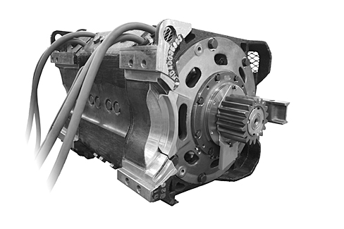
Above: A typical traction motor removed from its truck
These are the key parts of the powertrain in a typical diesel-electric locomotive. We will cover braking later on, as brake equipment gets very complex. Now let's move on to the controls.
Engine Controls/Indicators#
-
Throttle: This is different from the throttle in an automobile in that it only has 9 positions, counting 0 (idle). These positions are referred to as IDLE, and RUN1 through RUN8, with RUN8 being the maximum power output the locomotive is capable of.
-
Ammeter/Load Indicator: This is a gauge that measures the electrical current (in amps) being used by the traction motors of the locomotive. It is used by the engineer as a rough estimate of the load on the locomotive. A photo of the ammeter in an F7 can be found in the operator's manual.
-
Speedometer: The look of a locomotive speedometer can vary widely depending on its age, but they all perform the same function. The F7 has a Barco Speed Recorder, while newer locomotives may be equipped with a digital speedometer like this one.
That's all for this chapter. Move on to "Horsepower and Tractive Effort" for a start into the physics behind the powertrain!